Camera-Robot Calibration Software Package
I developed an automated regime for calibrating a multi-camera system with a UR5 robotic arm, in collaboration with a fellow student. The software is written in Python in a Ubuntu environment and also makes use of the Robotic Operation System (ROS). The package has been used successfully by members of the Australian Centre for Robotic Vision.
The software is setup to automatically obtain the transformation matrices between the camera(s), the base of the robot arm, the end-effector of the robot, and also optionally the work station (table). These reference frames are illustrated below. The camera parameters (focal length, principle point, etc) are also computed and provided in the typical Intrinsic matrix format.
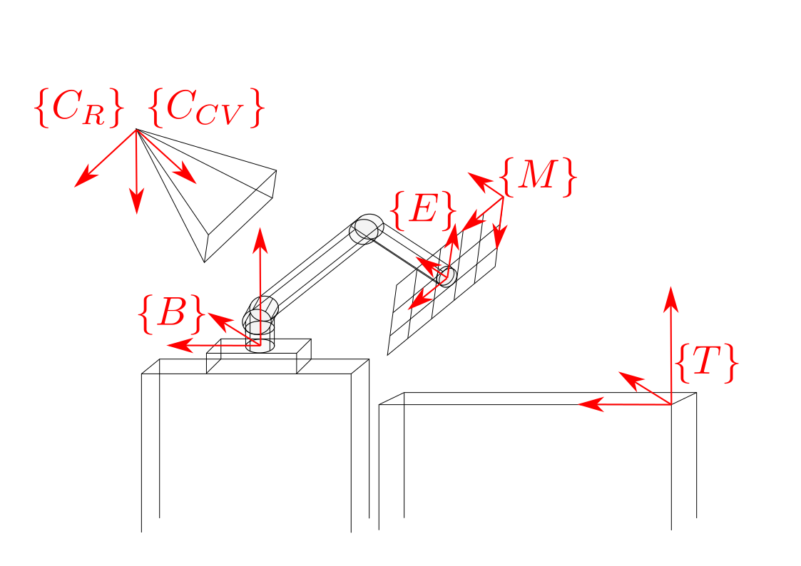 Fig 1. Illustration of reference frames computed by this software.
The software makes use of an Aruco-marker board, which is a common tool for camera calibration. The board is attached via a custom-made joint. The CAD model for the joint is also provided. Below is an illustration of the software package in action.
 Fig 2. Calibration In-action.
The user-guide for the software package is provided below, and is also provided on the Github page.
Mutli-Camera - UR5 Robotic Arm Calibration Package
![]()
Package Overview
This software package demonstrates a strategy of calibrating multi-cameras’ intrinsics and poses with respect to the manipulator’s base frame. This repository contains the main calibration script, required hardware CAD files, and a data collection example script.
This software is designed for UR5 manipulator, however the overall calibration strategy is general and other robotic or camera platforms can be integrated if the robot forward kinematics is provided.
Prequisites
This repository is tested under python 2.7. If the dataset is provided with the given file structure, the calibration can be executed without ROS. However, running the data collection example does require ROS.
The data collection script is tested on ur5 with firmware 13.xx
ChAruco calibration boards can be generated here.
File Structure
./dataset
+-- dataset1
|  +-- out.json
|  +-- cam_0
|  |  +-- images
|  |  |  +-- 000.png
|  |  |  +-- ...
|  |  +-- meta
|  |  |  +-- 000.json
|  |  |  +-- ...
|  |  +-- table*
|  |  |  +-- images
|  |  |  |  +-- ...
|  |  |  +-- meta
|  |  |  |  +-- ...
|  +-- cam_1
...
The calibration script scans the sub-directories in a given dataset, each sub-directory contains the sample associated with one camera, including a images and a meta folder. The *.json file for each sample has the joint angle of the manipulator and corresponding image name. The table folder is optional, it uses the calibration parameter associated with the directory it is in to estimate the table surface height w.r.t the manipulator’s base frame.
Run the program
Type python run.py -h for detailed description of the optional arguments.
Implementation
The code is designed to calibrate the setup shown in Figure 1.
where {C_CV} refers to camera pose using the Computer Vision convention, {C_R} refers to camera pose using the Robotics convention, {M} refers to the ChAruco Marker board, {E} refers to end-effector pose, {B} refers to the pose of the UR5 base, and {T} refers to the pose of the table.
The code computes the poses the pose of the camera, table, and end-effector with respect to the base of the UR5. The pose of the table is defined as being the pose of the calibration board when the board is sitting flat on the table. Thus, only the axis orthogonal to the table will remain constant as the checkerboard moves around the plane of the table.
A more detailed overview of the calibration process is provided in documents/formulation.pdf.
Required Skills
- Python
- Robot Operating System (ROS)