
Lightfield Photography
The light field is the full description of light as it travels in all directions through space around us. It can be thought of as being made up of infinitely many light ray vectors, each with a direction of propagation and a magnitude that is proportional to their intensity. In this post I provide an introduction to the lightfield and lightfield photography.
Lightfield Photography
As humans, we view the world by interpreting the intensity and frequency of the subset of light rays that intersect our eyes. However, our eyes, just like standard cameras, are incapable of recording the direction of these light rays. Recording the direction of these light rays allows for the light field to be fully defined at a given location. Light field photography allows the direction of light rays to be captured. This means that a higher dimensional representation of light is captured by a light field camera compared to a standard camera. Light field cameras therefore provide a new, more detailed way of sensing light in an environment. This dense sensor information is already being applied to existing applications within the research fields of robotics and computer vision. Such applications include odometry, depth mapping, 3D image reconstruction, and image filtering. By capturing more information about a scene, these applications are able to gain more information from a single image. For example, 3D image reconstruction requires multiple images of a scene to be taken taken from different, known camera poses. This method is referred to as ‘stereo vision’. The directional dimensions that are added by taking multiple standard images are captured in a single light field image.
Light
Visible light propagates through space as part of the electromagnetic spectrum. This part of the electromagnetic spectrum incorporates frequencies of between 430 and 700 Terahertz (THz), and contains within it all the colours that we see. These colours are visible to us due to the different frequencies at which light is reflected and absorbed by different objects. Light can also be deflected when it passes through an object, in a phenomenon known as refraction. It is refraction that allows light to be focused by a lens onto an image sensor.
The Image Sensor
Image sensors come in two main varieties: Complementary Metal Oxide Semiconductor (CMOS), or the older Charge-Coupled Devices (CCD). When the image sensor is exposed, photons hit the photoactive areas on the sensor, called ‘pixels’, and an electrical charge is produced. It is the differing ways in which these charges are produced that differentiates CMOS and CCD sensors. Placing a filter, such as a Bayer filter, over the pixels on a sensor allows the frequency of light to dictate the amount of electric charge produced. Pixels can therefore be used to determine the intensity of different colours within a scene. Intensity is often also referred to as ‘irradiance’ and is a measure of power per unit area. These filters comprise of patterns of colour filters that allow different wavelengths of light through (see Figure 1). The missing information between consecutive colour filters of the same type is added to the scene via interpolation to create the final image.
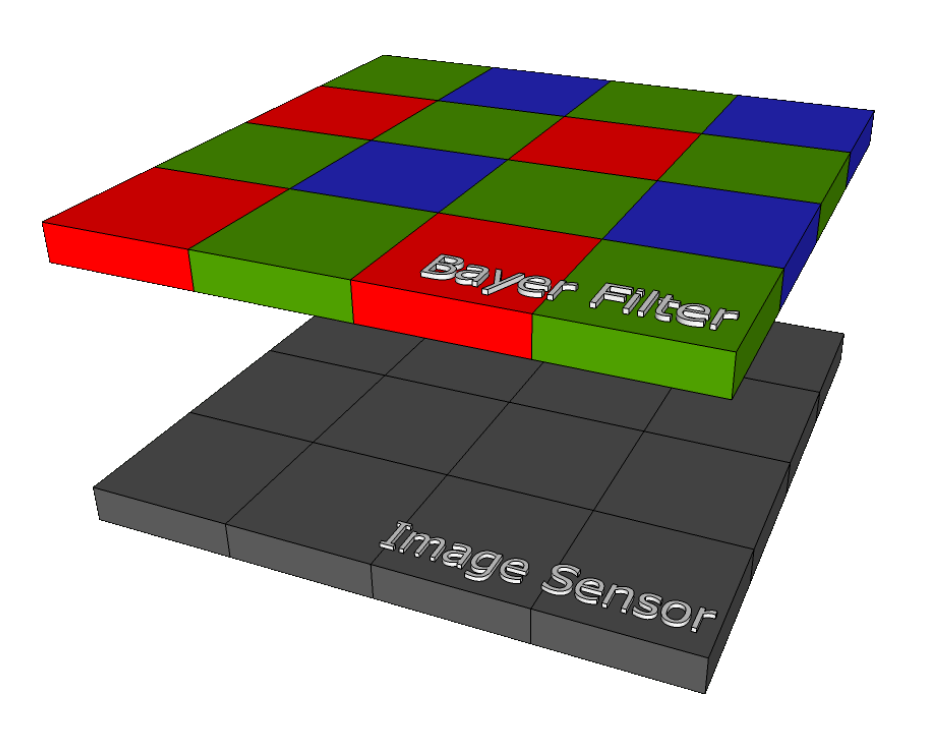 Fig 1. Bayer filter above image sensor pixels1.
Cameras
In a standard camera, light is focused by a lens, through a filter, onto an image sensor. When this sensor is exposed the pixel responses are integrated over the exposure duration. The image that is produced has a single plane of focus that is dictated by the distance between the lens and the sensor (the focal length). Parts of the scene that are not within the plane of focus are recorded by the sensor as unfocused, blurry spots. This is because light rays propagating from these depths are not precisely focused on to the sensor by the lens. However, capturing the full light field, rather than just the summation of photon responses, allows for light rays at all depths to be focused on to the sensor.
The Light Field
While the true behaviour of light is complicated, its movement through space is usually simplified to a light ray vector for image-based applications. This simplification allows the direction and intensity of light rays to be conserved while the more complicated properties of light are ignored. Each light ray is the result of reflection of light by a body, and contains within it a projection of that body. This projection can be captured by a camera at a given location. For example, a pin-hole camera works by capturing a small subset of these rays, and will capture a different subset (and thus a different perspective) depending on its location relative to the body (see Figure 2). It is therefore not only the intensity of light rays, but also their orientation and direction (i.e. their angle of incidence) that dictates the resultant image. It follows that to fully describe the behaviour of light as it flows through a camera lens to the image sensor, one must quantify not only the intensity of the light rays in this volume, but also their orientation and direction. This full description of light rays is what is known as the light field. The light field can therefore be thought of as the infinite collection of light ray vectors, each with a magnitude proportional to their intensity, that exists around us2. The question that arises at this point is, how many dimensions are required to fully define light ray vectors?
 Fig 2. Light rays reflecting off a body and being captured by a pin-hole camera.
In 1991 Adelson and Bergen were the first to provide the answer to this question with their Plenoptic Function, which has a 7-dimensional (7D) input 1. This function, derived from the Latin word plenum meaning ‘full’, contains 3 spatial coordinates, 2 directional coordinates, 1 time coordinate and 1 frequency coordinate 3. These 7 dimensions fully define a light field. However, not all 7 dimensions need to be captured to fully define a light field for light field photography applications. For example, it can be seen immediately that time is unnecessary for static images. Frequency is also not required, as it can be replaced with the 3 channels of a colour space implemented with a filter such as a Bayer filter 3. Finally, one of the spatial coordinates is unnecessary, as the nature of a light ray does not change along the axis of propagation unless it is blocked 4. We are therefore left with a 4D subset of the Plenoptic function that fully describes the light field for light field photography applications.
The Light Field Camera
To take a standard photograph the intensity of the light field is recorded at a pixel by integrating over all individual light ray contributions at that point. A standard image therefore represents a 2D array of values, each corresponding to the intensity of the light field at that location. However, to capture the full light field at each location, rather than just the intensity, the direction of the light rays intersecting that point must also be recorded.
A variety of different methods have been proposed and implemented to capture this 4D light field. A comprehensive list of typical methods, with links to the corresponding literature, is available in 5. The four key areas within which these methods can be categorised are: ‘multi-sensor’, ‘time sequential’, ‘frequency multiplexing’, and ’spatial multiplexing’ 5. Of these four methods, spatial multiplexing is dealt with here, as the Lytro camera falls into this category. Spatial multiplexing involves capturing \an interlaced array of elemental images representing samples from different 2D slices of the light field” 5.
Four key approaches to spatial multiplexing, along with a list of corresponding cameras within, is provided in 6. These approaches can be summarised as follows:
- a main lens focusing onto an array of micro-lenses over an array of detectors of the same dimensions,
- a micro-lens array over a photo sensor,
- aspherical lenses used to create depth-specific blur, and
- a main lens focusing on to an array of micro-lenses over an image sensor 6.
The Micro-lens Array
The Lytro employs an array of ∼130,000 hexagonally arranged micro-lenses placed ∼25µm (one focal length) from the image sensor 7. Light rays are initially focused by the camera’s main lens, just as is the case in a regular camera. However, instead of the light rays then striking the image sensor, they are re-focused on to the image sensor by the micro-lens array 6. Micro-lenses can be thought of as the pixels in a standard camera, while pixels in a light field camera are used to determine light ray direction, as discussed below.
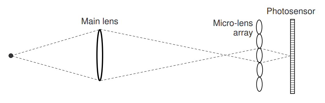 Fig 3. The Lytro’s lens configuration.
For this configuration to be capable of capturing the light field within the camera lens, all 4 dimensions of the reduced Plenoptic function must be captured. The two-plane parameterisation that is used to accomplish this can be expressed as P = L(x; y; u; v), where P is the Plenoptic Function, L is the light field, and (x; y; u; v) are spacial coordinates, with (x; y) representing the sensor plane, and (u; v) representing the micro-lens plane. The relationship of the spatial coordinates is illustrated in Figure 4.
 Fig 4. Two-plane plenoptic parameterisation. The same ray is represented from 3 different angles to illustrate the angles θx and θy.
The orientation and direction of a light ray can be characterised by its x and y coordinate, and its direction (θx and θy). While this clarifies how the two-plane parametrisation can be used to obtain the direction and orientation of a light ray, it may still be unclear how these values (x; y; u; v) are measured in the first place. Excellent discussions of how the (x; y; u; v) values are recorded in lens-array based light field cameras can be found in 8 9. These discussions are summarised here. To measure the angle of incidence of light rays, it must be remembered that there are many pixels underneath each micro-lens. Using a method that is similar to Single Lens Stereo (see 9 for a description of this technique), the angle of incidence can be determined by tracking which individual pixels have been reached by each light ray. Figure 5 provides an illustration of how different combinations of pixel responses indicate different locations of the subject, by displaying two such locations.
 Fig 5. Correlation between subject location and pixel response. Light propagating from different points will reach different combinations of pixels under the microlenses. The parametrisation L(x; y; u; v) is also shown.
Using the location of the pixels struck by a light ray, the corresponding micro-lens (the x; y coordinates) can be determined, as can the corresponding location on the main lens (the u; v coordinates) 6. From these coordinates, the direction of the light ray can be determined 8. The location of pixel responses therefore provides all the information required for the full L(x; y; u; v) parameterisation, thus allowing light field images to be captured by the Lytro.
Light Field Image Rendering
The micro-lens array in light field cameras causes an array of ‘micro-images’ of the scene to be captured, one beneath each micro-lens. These micro-images can be transformed to ‘macro-images’ (standard images of the full scene) by summing all the pixels beneath each micro-lens 8. The micro-images are all slightly different due to their location relative to the main lens. This difference illustrates the capture of the extra, spacial coordinates by the micro-lens based light field camera. By choosing only pixels that correspond to a certain direction within the main lens aperture, the resultant macro-image will appear to have been captured from that direction 8 10. For example, selecting the centre pixel beneath each micro-lens will produce the centre macro-image. Likewise, the depth of field can be varied by summing over a wider or thinner band of pixels beneath each micro-lens 8.
A. Software. Bayers filter. Available: https://azzlsoft.com/tag/bayer-filter. ↩ ↩2
B. J. Adelson E, “The plenoptic function and the elements of early vision” Computational Models of Visual Processing, pp. 3-20, 1991. ↩
D Dansereau, “Plenoptic signal processing for robust vision in field robotics”, Ph.D. thesis, Sydney University, 2014. ↩ ↩2
H. P. Levoy M, “Light field rendering,” ACM, pp. 31-42, 1996. ↩
G. Wu, B. Masia, A. Jarabo, Y. Zhang, L. Wang, Q. Dai, T. Chai, and Y. Liu “Light field image processing: An overview,” IEEE Journal of Selected Topics in Signal Processing, vol. PP, no. 99, pp. 1-1, 2017. ↩ ↩2 ↩3
Ng R, Levoy M, “Light field photography with a hand-held plenoptic camera”, Technical Report, Stanford University, 2005. ↩ ↩2 ↩3 ↩4
J. Kucera (2014), “Lytro Meltdown”, Available: “http://optics.miloush.net/lytro/” ↩
J. Kucera, “Computational Photography of Light-field Camera and Application to Panoramic Photography”, Master’s thesis, Charles University, Prague, 2014. ↩ ↩2 ↩3 ↩4 ↩5
W. J. Adelson, “Single lens stereo for plenoptic camera”, IEEE Transactions on Pattern Analysis and Machine Intelligence, vol. 14, pp. 99-106, 1992. ↩ ↩2
R. Ng, “Digital light field photography”, Ph.D. thesis, Stanford University, 2006. ↩